Nathan Evans

Audio Mixer & Splitter
Design Overview
- This audio splitter and mixer takes in one input from a bluetooth device, and splits it into two 3.5mm audio jacks
- Not only does this device split the single source into two, the user is also able to adjust the treble, mid-range, and bass via dials on the top
- I decided to have the input split into two audio channels to create left and right audio
- I also added in the functionality of bluetooth while all being powered by a common 15V AC to DC cord
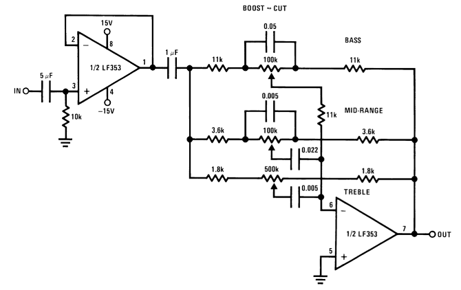
- I began by testing the circuit above via breadboarding
- This test did not account for bluetooth integration or the power source since I used one of the lab power sources to power the op-amps
Preliminary Design Verification
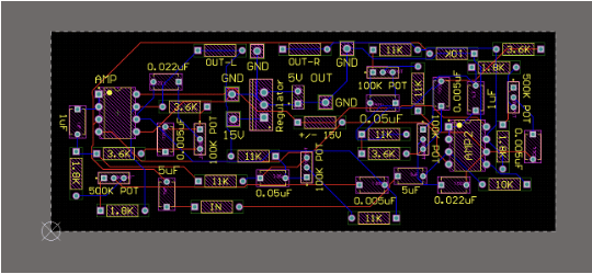
- I tried to match the resistors and capacitors to the design exactly but not all were available in the lab
- In the picture above, there are 5 capacitors in parallel. For the final design, I knew that this was not practical, but I just wanted to ensure the success of the circuit that was provided by Texas Instruments.
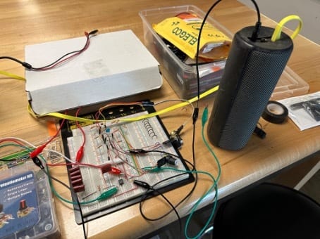
- Once the circuit was built, I began testing by plugging in a portable bluetooth speaker to the output and my laptop to the input
- Since my design is an audio splitter, the output heard from the speaker is either the left or right channel (whichever contact I choose to connect from the 3.5mm jack)
- I knew that we did not have some of the exact component values called for from the original schematic, so I began testing different resistors and capacitors to ensure that the final audio output was not distorted
Design Implementation
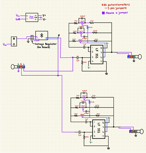
- As shown in the photo to the right, I planned to include two separate circuits onto the same board
- In addition to both circuits I planned to add a bluetooth receiver so that the splitter/mixer could be controlled via any bluetooth device
- I also wanted to power this device through one cable instead of multiple power inputs, so I added a voltage regulator for the bluetooth module to be powered from
- Another challenge with the design was powering the op-amps. Since they need +/- power, I had to find a separate power source that would be able to perform this conversion

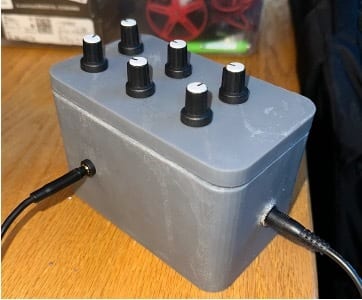
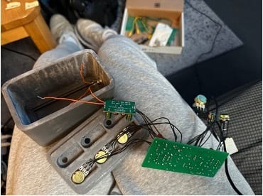
- I wanted to keep the enclosure design very simple by only having dials on the top, and the outputs on each side
- I decided to resin print the entire design because I thought that the robustness of the resin prints aided in the protection of the circuit
- I also had a fairly complicated lid design that would house the potentiometers, so I needed the enclosure to be nearly exact with the dimensions
- I wanted to create a board that was very compact, but there were so many individual components that it was difficult to implement all of these in such a small area while only using two layers
- After I thought that I had the layout correct, I realized that there was a wire that was connected to the incorrect pin, so I had to redo the schematic and check again to make sure that the design was flawless.
Design Testing
- One of the main problems that I ran into during the construction process was with the 3.5mm input jacks
- These were very cheaply made, so when I went to solder on a wire to the leads, one of the leads completely melted off
- Since this was supposed to be one of the input ports, I switched the course of the design to be a bluetooth only audio mixer
- Luckily, this mistake happened before the enclosure was created, so I was able to adjust the design to account for this change
- I was slightly worried about the 3.5mm inputs being pulled out of their housings, so I hot glued these to the enclosure
- I also hot glued the potentiometers to the lid even though they were already very secure
- I began by soldering the PCB together
- In order to test this board, I simply connected to the bluetooth module, and then connected the output to my external stereo system
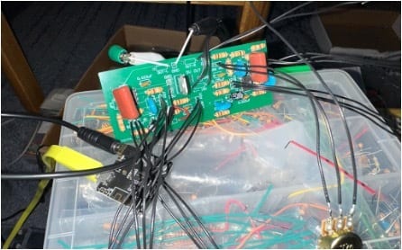
- The photo to the left shows the board with some of the potentiometers soldered to it
- As you can see at the top of the photo, there is a green and a black cable that are connected to the aux cable leading from the audio out on the board
- I would then begin turning each potentiometer to ensure that the direction was correct, and it was adjusting the correct range
- I would then mark each of the potentiometers with tape, so that when I placed them into the enclosure, I was sure which one was which