Nathan Evans
The requirements for this project were to build a “Bop-It!” styled toy which required at least 3 actions and provided feedback to the user. We elected to theme our toy off a beer can with our three actions being to open or pop the can, shake the can, and pour the can. In order to implement these actions in hardware we elected to utilize a simple push button for the opening of the can, an accelerometer for shaking the can, and a tilt switch oriented correctly to the spout of the can for the pouring mechanism. The primary logic would be running on an ATMega328p microprocessor configured the same as the open-source Arduino chipset in order to simplify programming. Additionally implemented would be a speaker powered by a DFRobot Mini MP3 Player which would allow for audio cues from a microSD card, alongside a 16x2 character display for displaying score information alongside written instructions for potential customers with auditory impairments. This display was initially intended to be an miniature OLED display however through testing we found that the memory requirements to run both the display and accelerometer exceeded the memory capacity of the microcontroller.
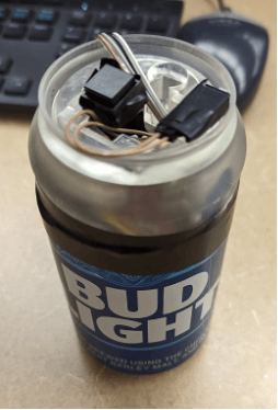
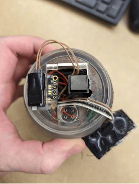


One main design challenge that we had to overcome was creating a board that was small enough to fit inside of a 12oz beer can. To combat this challenge, we opted to have jumpers from the board to the auxiliary components. Since some of the components’ actual footprints would have taken up too much space on the physical PCB, having jumpers to each pin allowed us to minimize the amount of space between each component’s jumpers.

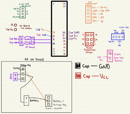
The photo in the upper right corner shows the high level design that we had for this project. From this drawing, I went into Altium to design the PCB board. The schematic is shown to the left and the final PCB that was printed is shown to the right.

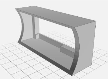
The last contribution that I made to this project was designing the enclosure for the components. I started by designing the enclosure with pillars on the sides to hold the PCB and help keep the rigidity of the can. There was also a hole created to allow the speaker to pass through the resin.
One problem that we ran into with this project was with our LCD screen. Our small screen that was ideal for the project was not compatible with the ATMega, so we opted for a larger screen. This screen proved to be a challenge because it was almost as large as the can, so the day before the project was due I had to create a housing that would hold this screen against the can.
These are recordings from my group mate that is the final demonstration. The video to the right is the demonstration of the final can. The video below is the demonstration of the can before it was assembled