Nathan Evans
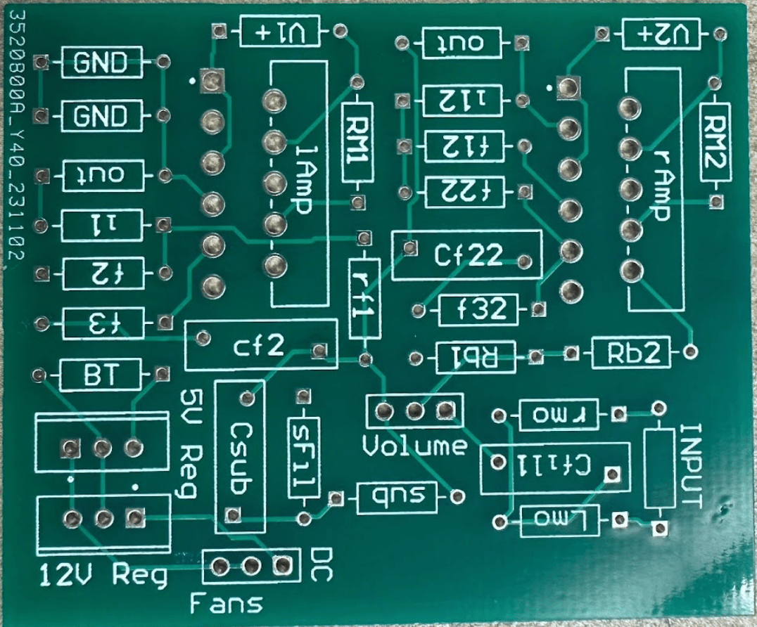
The PCB was a 2-layer board that was designed using Altium and was printed by JLCPCB. The board layout consisted of 3 separate modules. The first 2 which took up the largest footprint were the amplifier circuits, and the 3rd was the subwoofer filter. All passive filters (resistors, capacitors, or inductors) were placed directly onto the board. The amplifier chips were meant to be placed onto the board, but they were prone to heating up and self-destructing, so jumper wires took their place as they were now in contact with heat sinks. Each of these heat sinks had their own 12V fan that was powered directly from the board. Not only were the fans powered by the board, but the bluetooth module was also powered from the board using a 5V voltage regulator connected to the fans 12V voltage regulator.
The final physical design step was that of the enclosure. Originally the project speaker enclosure was envisioned to be constructed with wood, but ⅛ inch thick wood was not as sturdy as the same thickness acrylic. For this reason, acrylic was chosen to house all 3 speakers. With regards to the color, the clear case was simply a preference and had no effect on the outcome of the project.
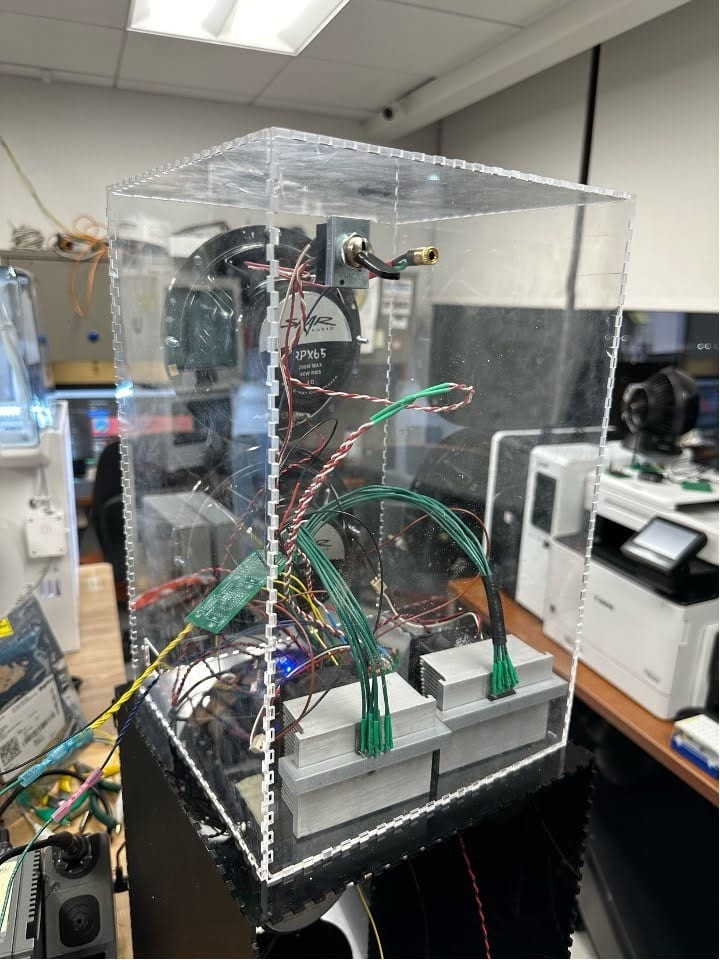
To actually construct the enclosure, a program called boxes.py was used to generate a box at the exact dimensions chosen. This file was then transferred to a laser engraver to make all of the fine cuts. In this laser engraving step, the ports for the speakers were also cut. For the dual speaker system enclosure, the dimensions were chosen to be able to house the PCB as well as the two heat sinks.

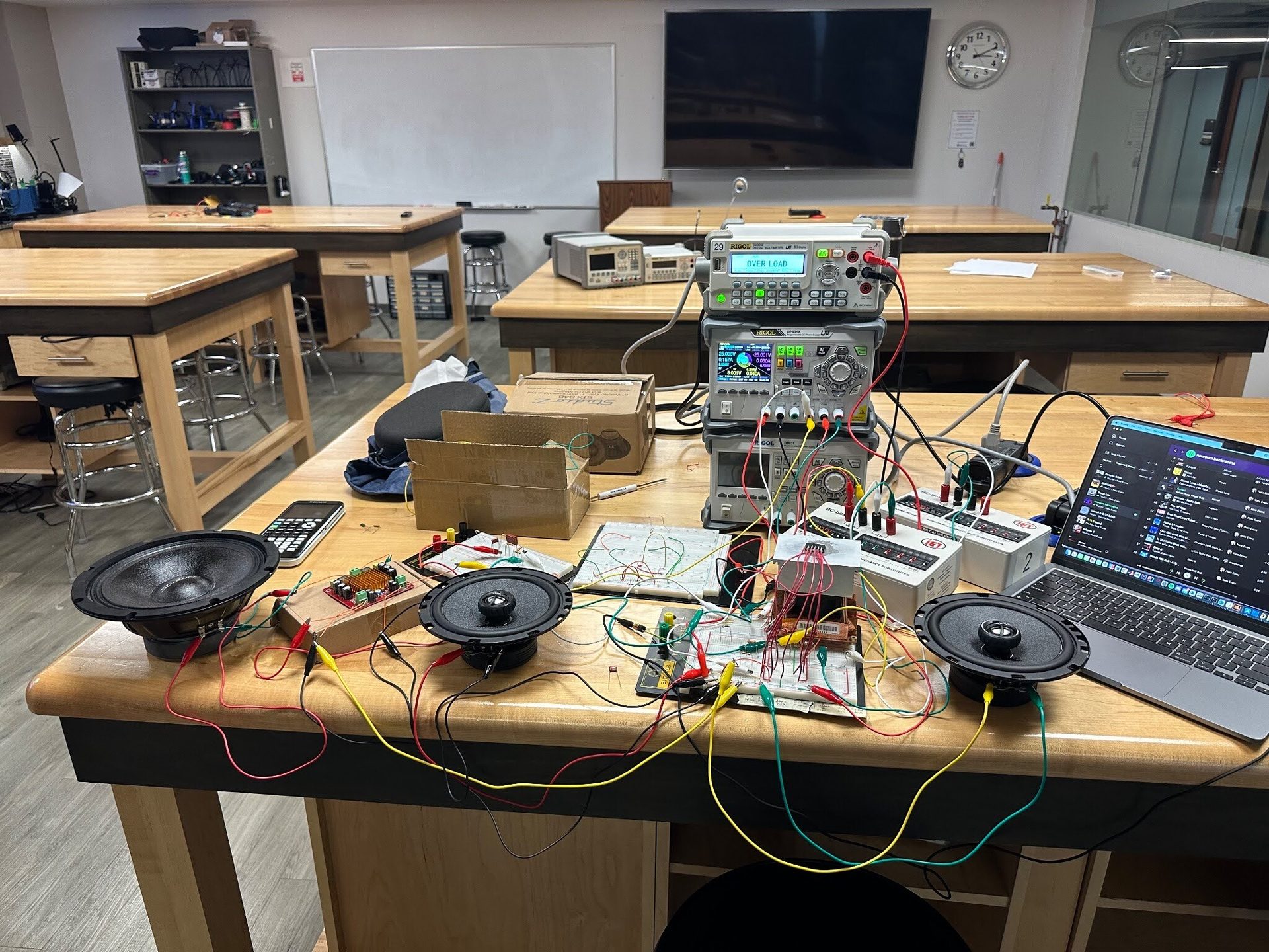
As seen in the image below, at 500 Hz, the graph begins to decrease. This is expected because the breadboard circuit is not ideal. Therefore, even though the cutoff frequency is supposed to be at 500 Hz and not allow any higher frequencies to pass through, it still allows frequencies close to this cutoff value but at a lower amplitude.